Richard spent three months working on his latest box diorama, and submitted the following pictures with brief descriptions charting the construction. He wrote: “Because the circuitry required both 220vAC and 5vDC, and I wanted to cut down on circuitry and cost, I used the 5vDC from a cell phone carger output, and took the 220vAC off the input. I used backlight material (behind the windows) for the picture of the outside environment, and I used flat micro LEDs for the lights inside the hangar, and a circular 220V 4W LED behind the backlight material.” The pictures tell the story, so enjoy!
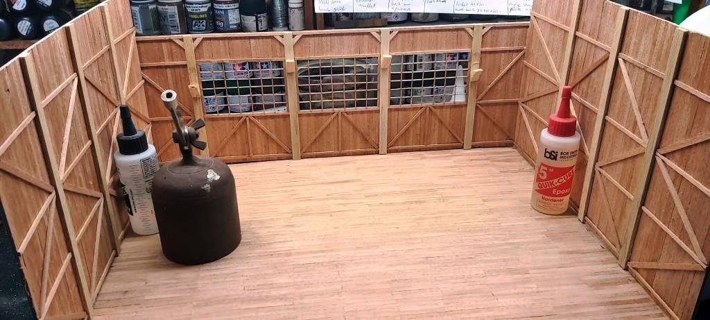

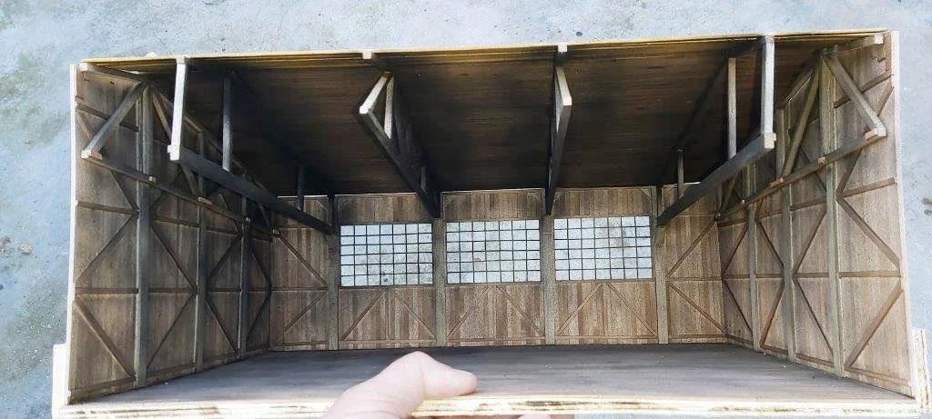
Above: The workshop floors and walls, the rafters, and the completed, weathered workshop.
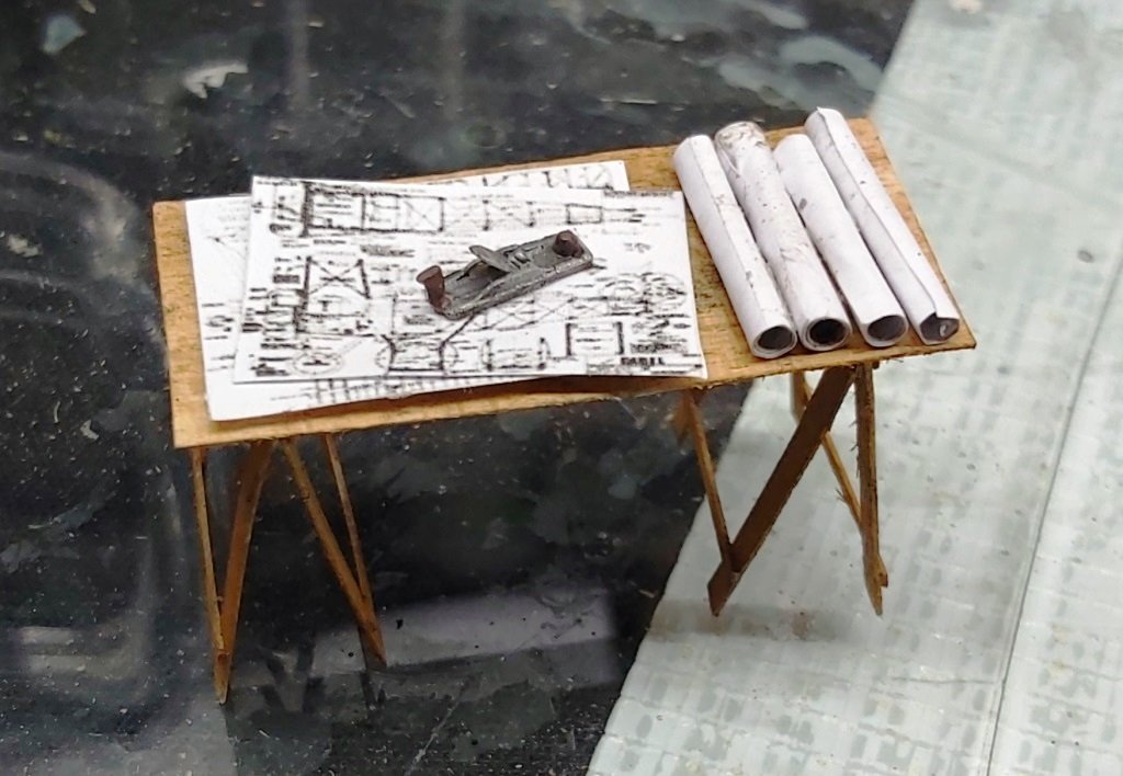
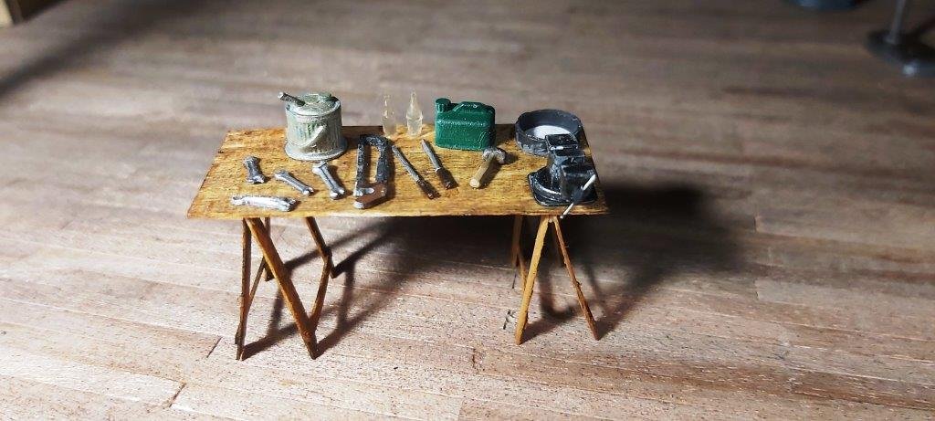
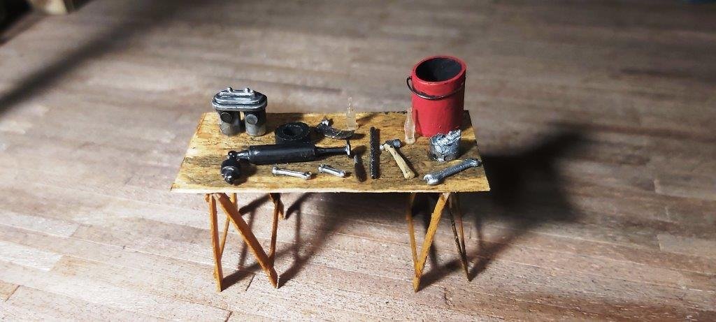
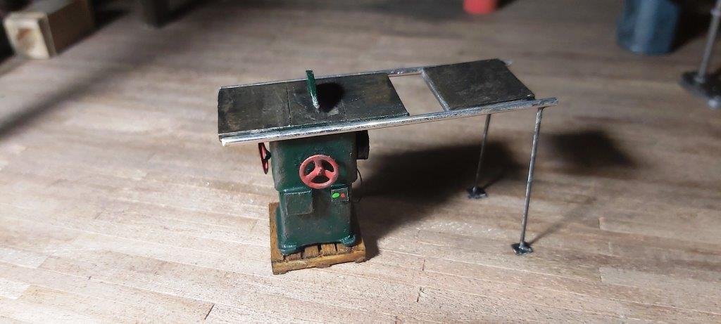
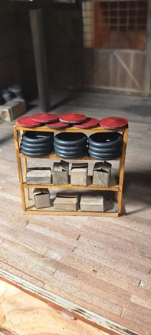
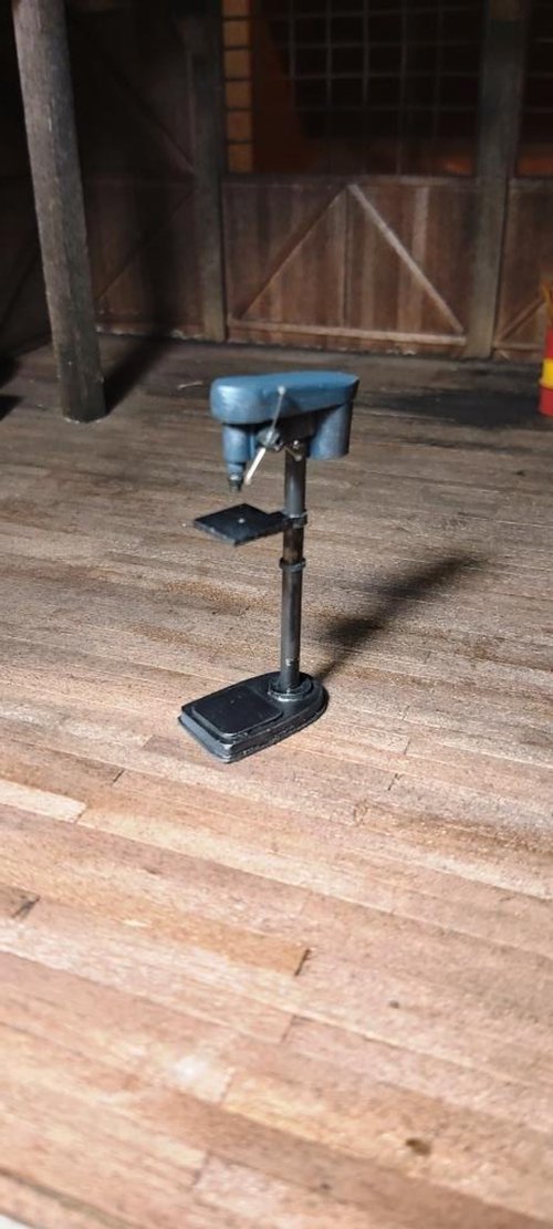
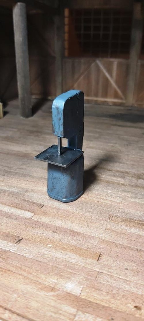
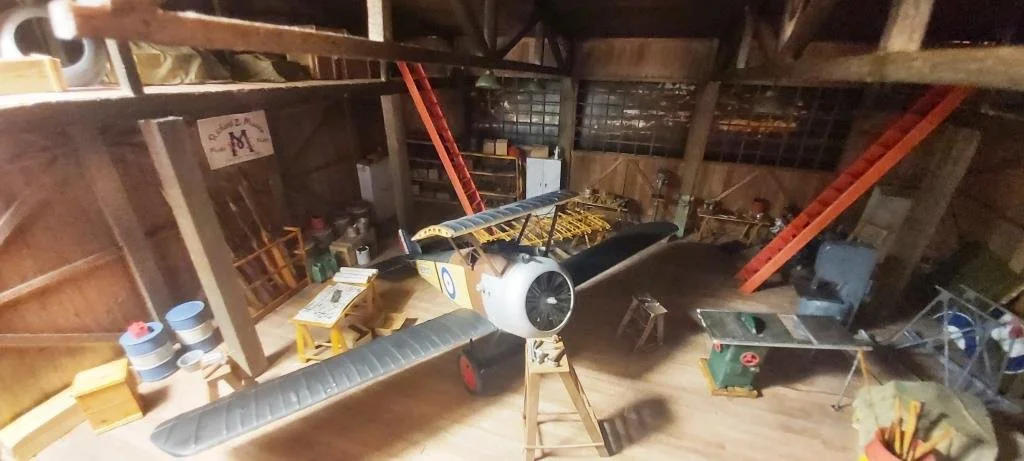
A series of photos Richard calls “making small bits” (above) and shots of the wing and rough positioning of the plane (below).


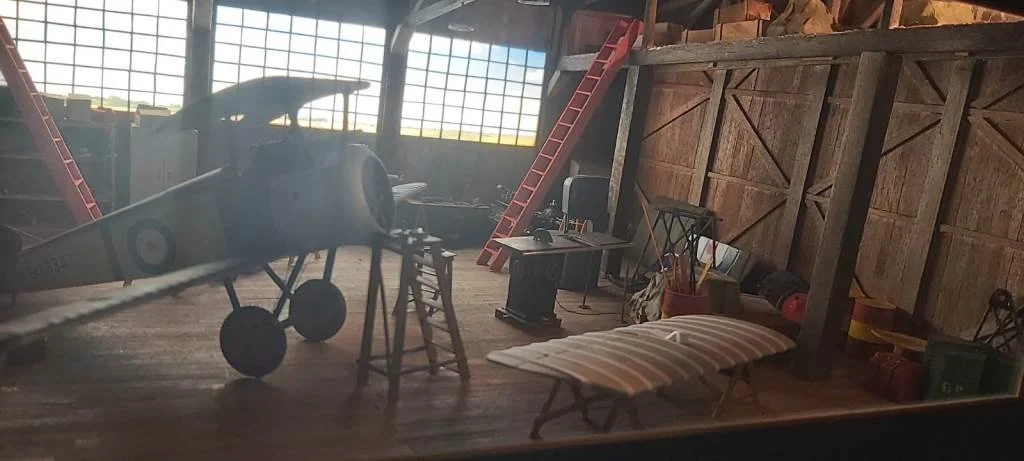
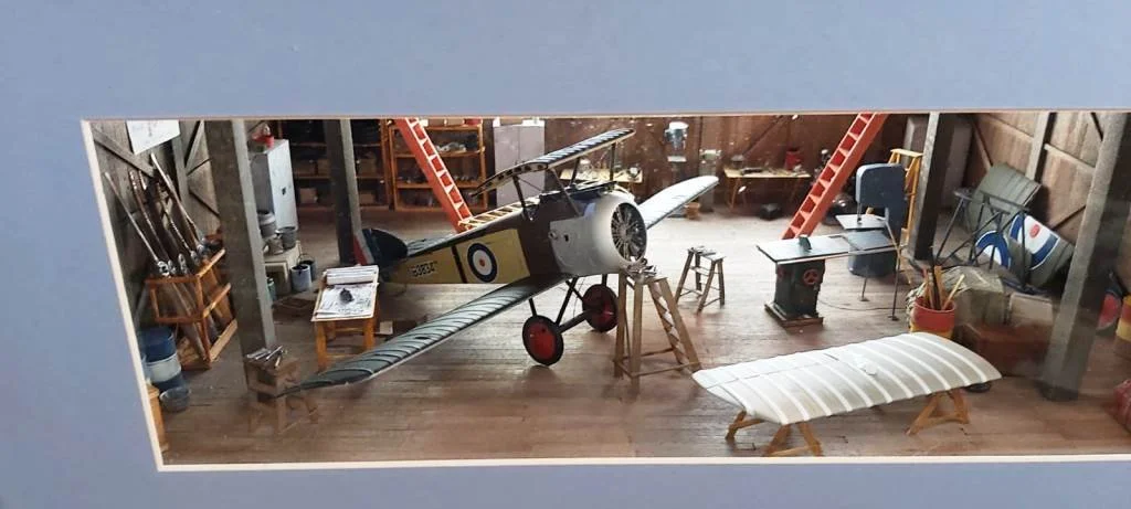
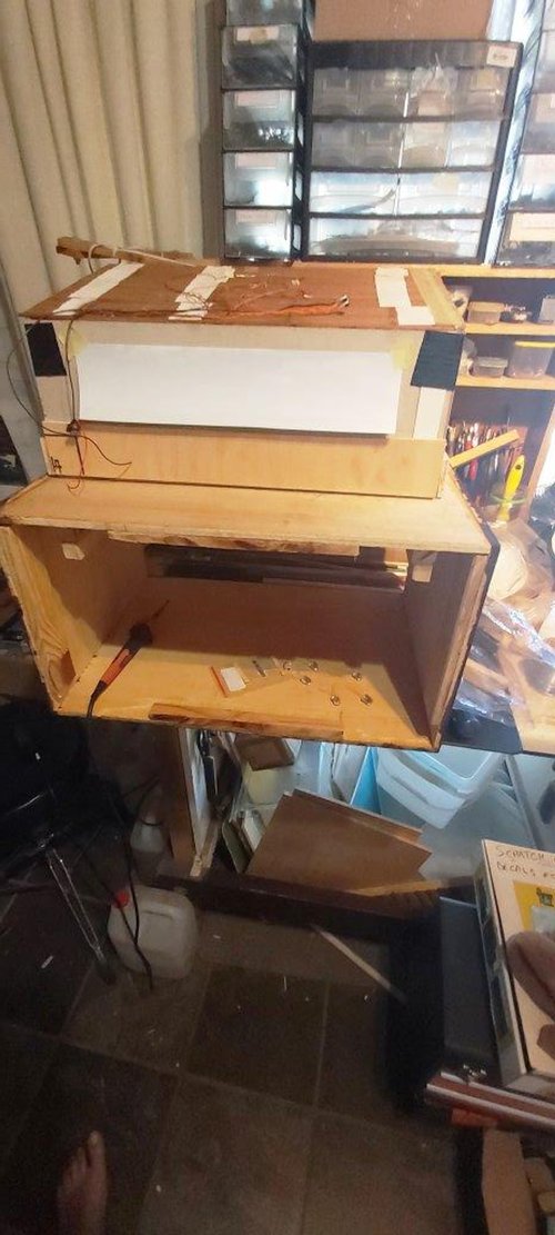
Below: The backdrop, testing the fit without the plane, and several pictures of everything in place.


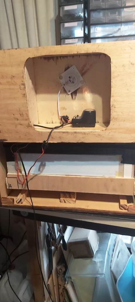
Below: The Electronics
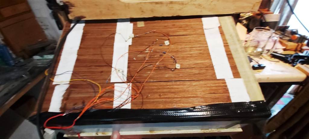
The phone charger, soldering the LEDs, and the soldered diodes.
And finally: Two more views of the finished box.